Chapter 3 Traps, interrupts, and drivers
When running a process, a CPU executes the normal processor loop: read an instruction, advance the program counter, execute the instruction, repeat. But there areevents on which control from a user program must transferred back to the kernel instead of executing the next instruction. These events include a device signaling that itwants attention, a user program doing something illegal (e.g., references a virtual address for which there is no PTE), or a user program asking the kernel for a servicewith a system call. There are three main challenges in handling these events: 1) thekernel must arrange that a processor switches from user mode to kernel mode (andback); 2) the kernel and devices must coordinate their parallel activities; and 3) thekernel must understand the interface of the devices well. Addressing these 3 challenges requires detailed understanding of hardware and careful programming, and canresult in opaque kernel code. This chapter explains how xv6 addresses these threechallenges.
Systems calls, exceptions, and interrupts
With a system call a user program can ask for an operating system service, as we sawat the end of the last chapter. The term exception refers to an illegal program actionthat generates an interrupt. Examples of illegal programs actions include divide by zero, attempt to access memory for a PTE that is not present, and so on. The term interrupt refers to a signal generated by a hardware device, indicating that it needs attention of the operating system. For example, a clock chip may generate an interruptevery 100 msec to allow the kernel to implement time sharing. As another example,when the disk has read a block from disk, it generates an interrupt to alert the operating system that the block is ready to be retrieved.
The kernel handles all interrupts, rather than processes handling them, because inmost cases only the kernel has the required privilege and state. For example, in orderto time-slice among processes in response the clock interrupts, the kernel must be involved, if only to force uncooperative processes to yield the processor.
In all three cases, the operating system design must arrange for the following tohappen. The system must save the processor’s registers for future transparent resume.The system must be set up for execution in the kernel. The system must chose a placefor the kernel to start executing. The kernel must be able to retrieve information aboutthe event, e.g., system call arguments. It must all be done securely; the system mustmaintain isolation of user processes and the kernel.
To achieve this goal the operating system must be aware of the details of how thehardware handles system calls, exceptions, and interrupts. In most processors thesethree events are handled by a single hardware mechanism. For example, on the x86, a program invokes a system call by generating an interrupt using the int instruction.Similarly, exceptions generate an interrupt too. Thus, if the operating system has aplan for interrupt handling, then the operating system can handle system calls and exceptions too.
The basic plan is as follows. An interrupts stops the normal processor loop andstarts executing a new sequence called an interrupt handler. Before starting the interrupt handler, the processor saves its registers, so that the operating system can restore them when it returns from the interrupt. A challenge in the transition to andfrom the interrupt handler is that the processor should switch from user mode to kernel mode, and back.
A word on terminology: Although the official x86 term is interrupt, xv6 refers toall of these as traps, largely because it was the term used by the PDP11/40 and therefore is the conventional Unix term. This chapter uses the terms trap and interrupt interchangeably, but it is important to remember that traps are caused by the currentprocess running on a processor (e.g., the process makes a system call and as a resultgenerates a trap), and interrupts are caused by devices and may not be related to thecurrently running process. For example, a disk may generate an interrupt when it isdone retrieving a block for one process, but at the time of the interrupt some otherprocess may be running. This property of interrupts makes thinking about interruptsmore difficult than thinking about traps, because interrupts happen concurrently withother activities. Both rely, however, on the same hardware mechanism to transfer control between user and kernel mode securely, which we will discuss next.
X86 protection
The x86 has 4 protection levels, numbered 0 (most privilege) to 3 (least privilege).In practice, most operating systems use only 2 levels: 0 and 3, which are then calledkernel mode and user mode, respectively. The current privilege level with which thex86 executes instructions is stored in %cs register, in the field CPL.
On the x86, interrupt handlers are defined in the interrupt descriptor table (IDT).The IDT has 256 entries, each giving the %cs and %eip to be used when handling thecorresponding interrupt.
To make a system call on the x86, a program invokes the int n instruction, wheren specifies the index into the IDT. The int instruction performs the following steps:
- Fetch the n’th descriptor from the IDT, where n is the argument of int.
- Check that CPL in %cs is <= DPL, where DPL is the privilege level in the descriptor.
- Save %esp and %ss in a CPU-internal registers, but only if the target segment selector’s PL < CPL.
- Load %ss and %esp from a task segment descriptor.
- Push %ss.
- Push %esp.
- Push %eflags.
- Push %cs.
- Push %eip.
- Clear some bits of %eflags.
- Set %cs and %eip to the values in the descriptor.
The int instruction is a complex instruction, and one might wonder whether allthese actions are necessary. The check CPL <= DPL allows the kernel to forbid systems for some privilege levels. For example, for a user program to execute int instruction succesfully, the DPL must be 3. If the user program doesn’t have the appropriate privilege, then int instruction will result in int 13, which is a general protection fault. As another example, the int instruction cannot use the user stack to savevalues, because the user might not have set up an appropriate stack so that hardwareuses the stack specified in the task segments, which is setup in kernel mode.
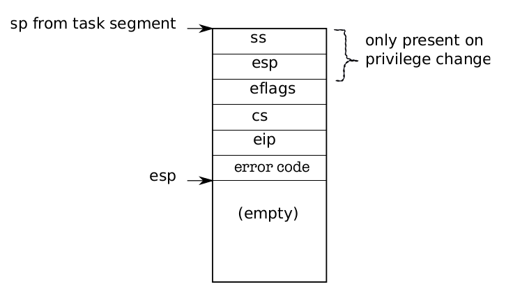
Figure 3-1. Kernel stack after an int instruction.
Figure 3-1 shows the stack after an int instruction completes and there was aprivilege-level change (the privilege level in the descriptor is lower than CPL). If theint instruction didn’t require a privilege-level change, the x86 won’t save %ss and%esp. After both cases, %eip is pointing to the address specified in the descriptor table, and the instruction at that address is the next instruction to be executed and the first instruction of the handler for int n. It is job of the operating system to implement these handlers, and below we will see what xv6 does.
An operating system can use the iret instruction to return from an int instruction. It pops the saved values during the int instruction from the stack, and resumesexecution at the saved %eip.
Code: The first system call
Chapter 1 ended with initcode.S invoking a system call. Let’s look at that again(7713). The process pushed the arguments for an exec call on the process’s stack, andput the system call number in %eax. The system call numbers match the entries in thesyscalls array, a table of function pointers (3350). We need to arrange that the int instruction switches the processor from user mode to kernel mode, that the kernel invokes the right kernel function (i.e., sys_exec), and that the kernel can retrieve thearguments for sys_exec. The next few subsections describes how xv6 arranges this forsystem calls, and then we will discover that we can reuse the same code for interruptsand exceptions.
Code: Assembly trap handlers
Xv6 must set up the x86 hardware to do something sensible on encountering anint instruction, which causes the processor to generate a trap. The x86 allows for 256different interrupts. Interrupts 0-31 are defined for software exceptions, like divide errors or attempts to access invalid memory addresses. Xv6 maps the 32 hardware interrupts to the range 32-63 and uses interrupt 64 as the system call interrupt.
Tvinit (3067), called from main, sets up the 256 entries in the table idt. Interrupti is handled by the code at the address in vectors[i]. Each entry point is different,because the x86 provides does not provide the trap number to the interrupt handler.Using 256 different handlers is the only way to distinguish the 256 cases.
Tvinit handles T_SYSCALL, the user system call trap, specially: it specifies thatthe gate is of type ‘‘trap’’ by passing a value of 1 as second argument. Trap gates don’tclear the FL flag, allowing other interrupts during the system call handler.
The kernel also sets the system call gate privilege to DPL_USER, which allows auser program to generate the trap with an explicit int instruction. xv6 doesn’t allowprocesses to raise other interrupts (e.g., device interrupts) with int; if they try, theywill encounter a general protection exception, which goes to vector 13.
When changing protection levels from user to kernel mode, the kernel shouldn’tuse the stack of the user process, because it may not be valid. The user process maybe malicious or contain an error that causes the user %esp to contain an address thatis not part of the process’s user memory. Xv6 programs the x86 hardware to performa stack switch on a trap by setting up a task segment descriptor through which thehardware loads a stack segment selector and a new value for %esp. The functionswitchuvm (1773) stores the address of the top of the kernel stack of the user processinto the task segment descriptor.
When a trap occurs, the processor hardware does the following. If the processorwas executing in user mode, it loads %esp and %ss from the task segment descriptor,pushes the old user %ss and %esp onto the new stack. If the processor was executingin kernel mode, none of the above happens. The processor then pushes the %eflags,%cs, and %eip registers. For some traps, the processor also pushes an error word.The processor then loads %eip and %cs from the relevant IDT entry.
xv6 uses a Perl script (2950) to generate the entry points that the IDT entries pointto. Each entry pushes an error code if the processor didn’t, pushes the interrupt number, and then jumps to alltraps.
Alltraps (3004) continues to save processor registers: it pushes %ds, %es, %fs, %gs, and the general-purpose registers (3005-3010). The result of this effort is that thekernel stack now contains a struct trapframe (0602) containing the processor registers at the time of the trap (see Figure 3-2). The processor pushes %ss, %esp,%eflags, %cs, and %eip. The processor or the trap vector pushes an error number,and alltraps pushes the rest. The trap frame contains all the information necessaryto restore the user mode processor registers when the kernel returns to the currentprocess, so that the processor can continue exactly as it was when the trap started.Recall from Chapter 2, that userinit build a trapframe by hand to achieve this goal(see Figure 1-3).
Figure 3-1. Kernel stack after an int instruction.
In the case of the first system call, the saved %eip is the address of the instructionright after the int instruction. %cs is the user code segment selector. %eflags is thecontent of the eflags register at the point of executing the int instruction. As part ofsaving the general-purpose registers, alltraps also saves %eax, which contains thesystem call number for the kernel to inspect later.Now that the user mode processor registers are saved, alltraps can finishing setting up the processor to run kernel C code. The processor set the selectors %cs and%ss before entering the handler; alltraps sets %ds and %es (3013-3015). It sets %fs and%gs to point at the SEG_KCPU per-CPU data segment (3016-3018).Once the segments are set properly, alltraps can call the C trap handler trap. Itpushes %esp, which points at the trap frame it just constructed, onto the stack as anargument to trap (3021). Then it calls trap (3022). After trap returns, alltraps pops the argument off the stack by adding to the stack pointer (3023) and then starts executing the code at label trapret. We traced through this code in Chapter 2 when thefirst user process ran it to exit to user space. The same sequence happens here: popping through the trap frame restores the user mode registers and then iret jumpsback into user space.
The discussion so far has talked about traps occurring in user mode, but trapscan also happen while the kernel is executing. In that case the hardware does notswitch stacks or save the stack pointer or stack segment selector; otherwise the samesteps occur as in traps from user mode, and the same xv6 trap handling code executes.When iret later restores a kernel mode %cs, the processor continues executing inkernel mode.
Code: C trap handler
We saw in the last section that each handler sets up a trap frame and then callsthe C function trap. Trap (3101) looks at the hardware trap number tf->trapno todecide why it has been called and what needs to be done. If the trap is T_SYSCALL,trap calls the system call handler syscall. We’ll revisit the two cp->killed checks inChapter 5.
After checking for a system call, trap looks for hardware interrupts (which we discuss below). In addition to the expected hardware devices, a trap can be caused by aspurious interrupt, an unwanted hardware interrupt.
If the trap is not a system call and not a hardware device looking for attention,trap assumes it was caused by incorrect behavior (e.g., divide by zero) as part of thecode that was executing before the trap. If the code that caused the trap was a userprogram, xv6 prints details and then sets cp->killed to remember to clean up theuser process. We will look at how xv6 does this cleanup in Chapter 5.
If it was the kernel running, there must be a kernel bug: trap prints detailsabout the surprise and then calls panic.
Code: System calls
For system calls, trap invokes syscall (3375). Syscall loads the system callnumber from the trap frame, which contains the saved %eax, and indexes into thesystem call tables. For the first system call, %eax contains the value SYS_exec (3207),and syscall will invoke the SYS_exec’th entry of the system call table, which corresponds to invoking sys_exec.
Syscall records the return value of the system call function in %eax. When thetrap returns to user space, it will load the values from cp->tf into the machine registers. Thus, when exec returns, it will return the value that the system call handler re-turned (3381). System calls conventionally return negative numbers to indicate errors,positive numbers for success. If the system call number is invalid, syscall prints anerror and returns –1.
Later chapters will examine the implementation of particular system calls. Thischapter is concerned with the mechanisms for system calls. There is one bit of mechanism left: finding the system call arguments. The helper functions argint and argptr,argstr retrieve the n’th system call argument, as either an integer, pointer, or a string.argint uses the user-space %esp register to locate the n’th argument: %esp points atthe return address for the system call stub. The arguments are right above it, at%esp+4. Then the nth argument is at %esp+4+4*n.
argint calls fetchint to read the value at that address from user memory andwrite it to *ip. fetchint can simply cast the address to a pointer, because the userand the kernel share the same page table, but the kernel must verify that the pointerby the user is indeed a pointer in the user part of the address space. The kernel hasset up the page-table hardware to make sure that the process cannot access memoryoutside its local private memory: if a user program tries to read or write memory atan address of p->sz or above, the processor will cause a segmentation trap, and trapwill kill the process, as we saw above. Now though, the kernel is running and it canderefence any address that the user might have passed, so it must check explicitly thatthe address is below p->sz
argptr is similar in purpose to argint: it interprets the nth system call argument. argptr calls argint to fetch the argument as an integer and then checks if theinteger as a user pointer is indeed in the user part of the address space. Note that twochecks occur during a call to code argptr . First, the user stack pointer is checked during the fetching of the argument. Then the argument, itself a user pointer, is checked.
argstr is the final member of the system call argument trio. It interprets the nthargument as a pointer. It ensures that the pointer points at a NUL-terminated stringand that the complete string is located below the end of the user part of the addressspace.
The system call implementations (for example, sysproc.c and sysfile.c) are typicallywrappers: they decode the arguments using argint, argptr, and argstr and then callthe real implementations. In chapter 2, sys_exec uses these functions to get at its arguments.
Code: Interrupts
Devices on the motherboard can generate interrupts, and xv6 must setup thehardware to handle these interrupts. Without device support xv6 wouldn’t be usable; auser couldn’t type on the keyboard, a file system couldn’t store data on disk, etc. Fortunately, adding interrupts and support for simple devices doesn’t require much additional complexity. As we will see, interrupts can use the same code as for systems callsand exceptions.
Interrupts are similar to system calls, except devices generate them at any time.There is hardware on the motherboard to signal the CPU when a device needs attention (e.g., the user has typed a character on the keyboard). We must program the device to generate an interrupt, and arrange that a CPU receives the interrupt.
Let’s look at the timer device and timer interrupts. We would like the timer hardware to generate an interrupt, say, 100 times per second so that the kernel can trackthe passage of time and so the kernel can time-slice among multiple running processes. The choice of 100 times per second allows for decent interactive performance while not swamping the processor with handling interrupts.
Like the x86 processor itself, PC motherboards have evolved, and the way interrupts are provided has evolved too. The early boards had a simple programmable interrupt controler (called the PIC), and you can find the code to manage it in picirq.c.
With the advent of multiprocessor PC boards, a new way of handling interruptswas needed, because each CPU needs an interrupt controller to handle interrupts sendto it, and there must be a method for routing interrupts to processors. This way consists of two parts: a part that is in the I/O system (the IO APIC, ioapic.c), and apart that is attached to each processor (the local APIC, lapic.c). Xv6 is designed fora board with multiple processors, and each processor must be programmed to receiveinterrupts.
To also work correctly on uniprocessors, Xv6 programs the programmable interrupt controler (PIC) (6932). Each PIC can handle a maximum of 8 interrupts (i.e., devices) and multiplex them on the interrupt pin of the processor. To allow for morethan 8 devices, PICs can be cascaded and typically boards have at least two. Usinginb and outb instructions Xv6 programs the master to generate IRQ 0 through 7 andthe slave to generate IRQ 8 through 16. Initially xv6 programs the PIC to mask all interrupts. The code in timer.c sets timer 1 and enables the timer interrupt on thePIC (7574). This description omits some of the details of programming the PIC. Thesedetails of the PIC (and the IOAPIC and LAPIC) are not important to this text but theinterested reader can consult the manuals for each device, which are referenced in thesource files.
On multiprocessors, xv6 must program the IOAPIC, and the LAPIC on each processor. The IO APIC has a table and the processor can program entries in the tablethrough memory-mapped I/O, instead of using inb and outb instructions. Duringinitialization, xv6 programs to map interrupt 0 to IRQ 0, and so on, but disables themall. Specific devices enable particular interrupts and say to which processor the interrupt should be routed. For example, xv6 routes keyboard interrupts to processor 0(7516). Xv6 routes disk interrupts to the highest numbered processor on the system, aswe will see below.
The timer chip is inside the LAPIC, so that each processor can receive timer interrupts independently. Xv6 sets it up in lapicinit (6651). The key line is the one thatprograms the timer (6664). This line tells the LAPIC to periodically generate an interrupt at IRQ_TIMER, which is IRQ 0. Line (6693) enables interrupts on a CPU’s LAPIC,which will cause it to deliver interrupts to the local processor.
A processor can control if it wants to receive interrupts through the IF flag in theeflags register. The instruction cli disables interrupts on the processor by clearing IF,and sti enables interrupts on a processor. Xv6 disables interrupts during booting ofthe main cpu (8412) and the other processors (1126). The scheduler on each processorenables interrupts (2464). To control that certain code fragments are not interrupted,xv6 disables interrupts during these code fragments (e.g., see switchuvm (1773)).
The timer interrupts through vector 32 (which xv6 chose to handle IRQ 0), whichxv6 setup in idtinit (1265). The only difference between vector 32 and vector 64 (theone for system calls) is that vector 32 is an interrupt gate instead of a trap gate. Interrupt gates clears IF, so that the interrupted processor doesn’t receive interrupts while itis handling the current interrupt. From here on until trap, interrupts follow the samecode path as system calls and exceptions, building up a trap frame.Trap when it’s called for a time interrupt, does just two things: increment theticks variable (3063), and call wakeup. The latter, as we will see in Chapter 5, may causethe interrupt to return in a different process.
Drivers
A driver is the piece of code in an operating system that manage a particular device:it provides interrupt handlers for a device, causes a device to perform operations, causes a device to generate interrupts, etc. Driver code can be tricky to write because adriver executes concurrently with the device that it manages. In addition, the drivermust understand the device’s interface (e.g., which I/O ports do what), and that interface can be complex and poorly documented.
The disk driver provides a good example in xv6. The disk driver copies datafrom and back to the disk. Disk hardware traditionally presents the data on the diskas a numbered sequence of 512-byte blocks (also called sectors): sector 0 is the first 512bytes, sector 1 is the next, and so on. To represent disk sectors an operating systemhas a structure that corresponds to one sector. The data stored in this structure is often out of sync with the disk: it might have not yet been read in from disk (the disk isworking on it but hasn’t returned the sector’s content yet), or it might have been updated but not yet written out. The driver must ensure that the rest of xv6 doesn’t getconfused when the structure is out of sync with the disk.
Code: Disk driver
The IDE device provides access to disks connected to the PC standard IDE controller. IDE is now falling out of fashion in favor of SCSI and SATA, but the interfaceis simple and lets us concentrate on the overall structure of a driver instead of the details of a particular piece of hardware.
The disk driver represent disk sectors with a data structure called a buffer,struct buf (3500). Each buffer represents the contents of one sector on a particulardisk device. The dev and sector fields give the device and sector number and thedata field is an inmemory copy of the disk sector.
The flags track the relationship between memory and disk: the B_VALID flagmeans that data has been read in, and the B_DIRTY flag means that data needs to bewritten out. The B_BUSY flag is a lock bit; it indicates that some process is using thebuffer and other processes must not. When a buffer has the B_BUSY flag set, we saythe buffer is locked.
The kernel initializes the disk driver at boot time by calling ideinit (3851) frommain (1234). Ideinit calls picenable and ioapicenable to enable the IDE_IRQ interrupt (3856-3857). The call to picenable enables the interrupt on a uniprocessor; ioapi-cenable enables the interrupt on a multiprocessor, but only on the last CPU (ncpu-1):on a two-processor system, CPU 1 handles disk interrupts.
Next, ideinit probes the disk hardware. It begins by calling idewait (3858) towait for the disk to be able to accept commands. A PC motherboard presents the status bits of the disk hardware on I/O port 0x1f7. Idewait (3833) polls the status bitsuntil the busy bit (IDE_BSY) is clear and the ready bit (IDE_DRDY) is set.
Now that the disk controller is ready, ideinit can check how many disks arepresent. It assumes that disk 0 is present, because the boot loader and the kernel wereboth loaded from disk 0, but it must check for disk 1. It writes to I/O port 0x1f6 toselect disk 1 and then waits a while for the status bit to show that the disk is ready(3860-3867). If not, ideinit assumes the disk is absent.
After ideinit, the disk is not used again until the buffer cache calls iderw,which updates a locked buffer as indicated by the flags. If B_DIRTY is set, iderwwrites the buffer to the disk; if B_VALID is not set, iderw reads the buffer from thedisk.
Disk accesses typically take milliseconds, a long time for a processor. The bootloader issues disk read commands and reads the status bits repeatedly until the data isready. This polling or busy waiting is fine in a boot loader, which has nothing better to do. In an operating system, however, it is more efficient to let another processrun on the CPU and arrange to receive an interrupt when the disk operation has completed.
Iderw takes this latter approach, keeping the list of pending disk requests in aqueue and using interrupts to find out when each request has finished. Althoughiderw maintains a queue of requests, the simple IDE disk controller can only handleone operation at a time. The disk driver maintains the invariant that it has sent thebuffer at the front of the queue to the disk hardware; the others are simply waitingtheir turn.Iderw (3954) adds the buffer b to the end of the queue (3967-3971). If the buffer isat the front of the queue, iderw must send it to the disk hardware by callingidestart (3924-3926); otherwise the buffer will be started once the buffers ahead of itare taken care of.
Idestart (3875) issues either a read or a write for the buffer’s device and sector,according to the flags. If the operation is a write, idestart must supply the data now(3889) and the interrupt will signal that the data has been written to disk. If the operation is a read, the interrupt will signal that the data is ready, and the handler will readit. Note that iderw has detailed knowledge about the IDE device, and writes the rightvalues at the right ports. If any of these outb statements is wrong, the IDE will dosomething differently than what we want. Getting these details right is one reasonwhy writing device drivers is challenging.
Having added the request to the queue and started it if necessary, iderw mustwait for the result. As discussed above, polling does not make efficient use of theCPU. Instead, iderw sleeps, waiting for the interrupt handler to record in the buffer’sflags that the operation is done (3978-3979). While this process is sleeping, xv6 willschedule other processes to keep the CPU busy.
Eventually, the disk will finish its operation and trigger an interrupt. trap willcall ideintr to handle it (3124). Ideintr (3902) consults the first buffer in the queue tofind out which operation was happening. If the buffer was being read and the diskcontroller has data waiting, ideintr reads the data into the buffer with insl (3915-3917). Now the buffer is ready: ideintr sets B_VALID, clears B_DIRTY, and wakes upany process sleeping on the buffer (3919-3922). Finally, ideintr must pass the next waiting buffer to the disk (3924-3926).
Real world
Supporting all the devices on a PC motherboard in its full glory is much work, because there are many devices, the devices have many features, and the protocol between device and driver can be complex. In many operating systems, the drivers together account for more code in the operating system than the core kernel.
Actual device drivers are far more complex than the disk driver in this chapter,but the basic ideas are the same: typically devices are slower than CPU, so the hardware uses interrupts to notify the operating system of status changes. Modern diskcontrollers typically accept multiple outstanding disk requests at a time and even reorder them to make most efficient use of the disk arm. When disks were simpler, operating system often reordered the request queue themselves.
Many operating systems have drivers for solid-state disks because they providemuch faster access to data. But, although a solid-state works very differently from atraditional mechanical disk, both devices provide block-based interfaces and reading/writing blocks on a solid-state disk is still more expensive than reading/writingRAM.
Other hardware is surprisingly similar to disks: network device buffers hold packets, audio device buffers hold sound samples, graphics card buffers hold video data andcommand sequences. High-bandwidth devices—disks, graphics cards, and networkcards—often use direct memory access (DMA) instead of the explicit I/O (insl, out-sl) in this driver. DMA allows the disk or other controllers direct access to physicalmemory. The driver gives the device the physical address of the buffer’s data field andthe device copies directly to or from main memory, interrupting once the copy is complete. Using DMA means that the CPU is not involved at all in the transfer, whichcan be more efficient and is less taxing for the CPU’s memory caches.
Most of the devices in this chapter used I/O instructions to program them, whichreflects the older nature of these devices. All modern devices are programmed usingmemory-mapped I/O.
Some drivers dynamically switch between polling and interrupts, because usinginterrupts can be expensive, but using polling can introduce delay until the driver processes an event. For example, for a network driver that receives a burst of packets,may switch from interrupts to polling since it knows that more packets must be processed and it is less expensive to process them using polling. Once no more packetsneed to be processed, the driver may switch back to interrupts, so that it will be alerted immediately when a new packet arrives.
The IDE driver routed interrupts statically to a particular processor. Some drivershave a sophisticated algorithm for routing interrupts to processor so that the load ofprocessing packets is well balanced but good locality is achieved too. For example, anetwork driver might arrange to deliver interrupts for packets of one network connection to the processor that is managing that connection, while interrupts for packets of another connection are delivered to another processor. This routing can get quite sophisticated; for example, if some network connections are short lived while others arelong lived and the operating system wants to keep all processors busy to achieve highthroughput.
If user process reads a file, the data for that file is copied twice. First, it is copiedfrom the disk to kernel memory by the driver, and then later it is copied from kernelspace to user space by the read system call. If the user process, then sends the dataon the network, then the data is copied again twice: once from user space to kernelspace and from kernel space to the network device. To support applications for whichlow latency is important (e.g., a Web serving static Web pages), operating systems usespecial code paths to avoid these many copies. As one example, in real-world operating systems, buffers typically match the hardware page size, so that read-only copiescan be mapped into a process’s address space using the paging hardware, without anycopying.
Exercises
- Set a breakpoint at the first instruction of syscall() to catch the very first system call(e.g., br syscall). What values are on the stack at this point? Explain the output ofx/37x $esp at that breakpoint with each value labeled as to what it is (e.g., saved %ebpfor trap, trapframe.eip, scratch space, etc.).
- Add a new system call
- Add a network driver